Example Alignments
Lens & Rotation Centre Alignment
Let’s begin with a tutorial using the simplest model our programme can produce: A beam, a single lens and a detector. Run the model “lens_example_pyqt” (via the .exe , or the python script), and become familiar with the interface. The important gui components are annotated in the image below.

With this basic model, we can demonstrate the principle of one of the direct alignments of a TEM, the rotation centre alignment. This alignment oscillates the current to the objective lens in a TEM, which in turn oscillates the focal length of the objective lens.
Using the information of how the spot responds, we can then adjust the tilt of the beam before the lens so that it lies paralell to the optic axis. In a real TEM, this is performed with an image of a sample or grid inside the TEM. We cannot easily model a sample in our model, but by visualising the beam spot we can recreate the behaviour of this alignment.
Tilt the beam off axis and turn on the lens wobble by ticking the check box “Wobble Lens Current”.

Rotation centre is misaligned, as the beam is away from the optic axis.
Notice how the beam moves accross the screen as the focal length changes. We wish to align the rotation centre by tilting the beam so that the spot no longer moves, and so that it only contracts in and out when the focal length changes. Bring the beam back onto the centre of the lens and thus paralell to the optic axis by adjusting the tilt of the beam. When the beam spot stops moving, the rotation centre is now aligned.

Rotation centre aligned.
Beam Tilt/Shift Alignment
In this basic model of the beam shift/tilt alignment, we use a pair of deflectors, a lens, and a detector to make the model interactive. For the beam shift and beam tilt alignment, the goal is to find the “deflector ratio” setting such that the beam purely shifts or purely tilts in the detector plane. The deflector ratio value is a multiplier which dictates how the lower deflector responds to a deflection provided by the upper deflector.
For example, if the upper deflector adds a deflection of 0.5 radians to the beam, and the deflector ratio is set to -1, the lower deflector will add a deflection of -0.5 radians to the beam, cancelling out the deflection from the upper deflector. This will then shift the beam over the sample and keep the beam paralell to the optic axis.
Another layer of complication is added because alignment manuals typically explain this alignment in terms of “Pivot Points”, and there is a seperate pivot point for both beam tilt and beam shift. Pivot points are simply where the beam pivots as a result of the settings of the deflector, and the location and focal length of a lens after it.


For a pure beam shift setting, the beam needs to go over the sample and into the lens paralell to the optic axis, and this will cause all rays to converge or “pivot” on the focal point of this lens (a.k.a the back focal plane). For beam tilt, the beam needs to pivot about a point on the sample before the lens, and this requires that our deflector ratio is set so that all rays go through the front focal plane, which is where the pivot point for beam tilt is located.
Also note that the deflector ratio that we need to find is a function of the distances between each component and of the focal length of the lens. When creating this model, we placed the components at convenient distances so that the deflector ratio for beam shift and beam tilt are convenient values.
Beam Shift Alignment
Run the basic Beam Shift/Tilt model and click the “Wobble Upper Deflector X” checkbox.

Set the deflector ratio to -1 and see that the spot on the detector is now stationary. You have correctly aligned the beam shift pivot point.
Beam Tilt Alignment
Now adjust the deflector ratio so that it is set to -2, and see that the beam tilts about a single point in the sample plane on the 3D viewer. Note that the beam will still oscillate on the detector, as another lens needs to be added to the model to image the beam tilt pivot point.
Condenser Astigmatism Alignment
In this alignment we introduce two new components, an astigmatic lens, and a stigmator. In our model, an astigmatic lens is simply a lens where the focal length can be adjusted on each axis. This captures the behaviour of a real lens in a TEM, which cannot perfectly focus in both x & y. This is because a real lens cannot be manufactured to be perfectly circular, and will thus have two different focal lengths on each axis. The component which is used to correct for this is a stigmator. This is composed of two quadrupole magnets which when the current to each is adjusted, can correct for astigmatism in a lens.
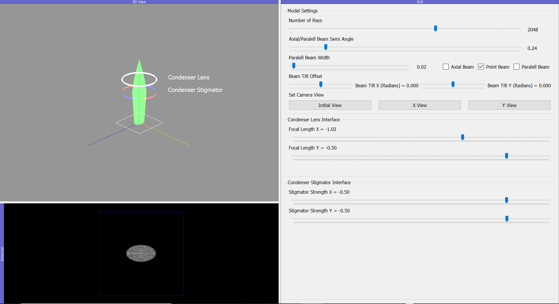
Elliptical beam indicates condenser asigmatism is misaligned
Load the “Condenser Asigmatism” alignment and adjust the axial width of the beam to make the spot larger. You can also adjust the number of rays so that the beam spot appears filled in, if your PC can handle a larger amount of rays. Adjust the focal length of the astigmatic lens until the beam appears elliptical. Note that in practise you as a user would not have control of the astigmatism of the lens! Use the condenser astigmatism sliders to correct for the astigmatism in the lens by making the beam appear round again.

Circular beam means we have corrected the condenser astigmatism
Condenser Aperture Alignment
Similar to almost every other alignment in the microscope, this alignment requires that the aperture is centred on the optic axis. Run the alignment “Condenser Aperture”, and adjust the strength of the condenser lens focal length.

Beamspot position before adjusting focal length.
Notice how as you do this, the beam spot appears to move accross the screen.

Beamspot position after adjusting focal length.
This happens because the aperture is not centred on the optic axis. Adjust the position of the aperture so that it is centred on the column, and adjust the focal length once more. Notice that the beam only changes size, and does not move accross the screen.